
In the previous post. I mention how to make a 1 time use bobbin. Now I am going to do windings in the bobbin, insulate it and put it into the E core.
Remember that bobbin I made?
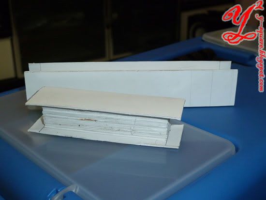
It has no holes, we(suppose to me my group mate and I but the uncle helped) have to drill 1 hole in the middle, so that we can attach it to the winding device.
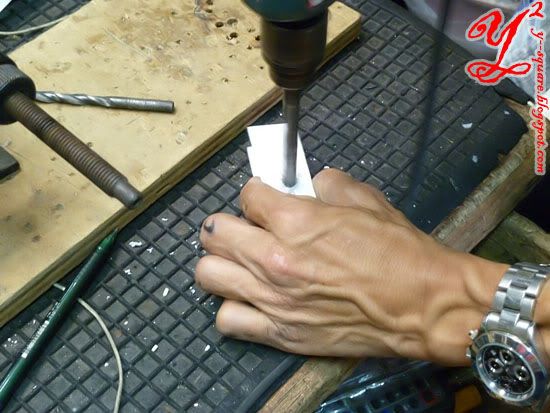
Drill the bobbin using electrical driller.
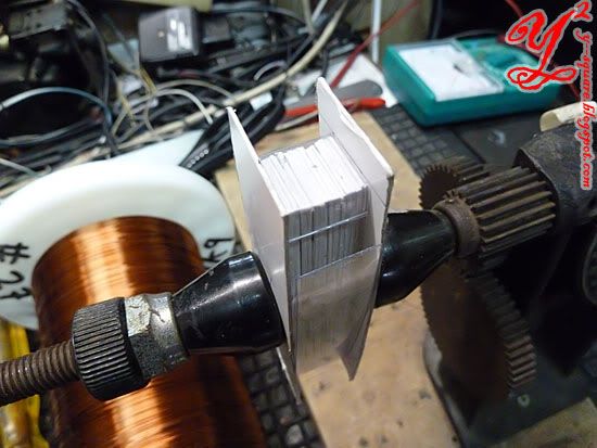
 It's very embarrassed that I didn't make the bobbin smooth enough, so I have to add a layer of plastic. If it happens to doing the same project, stupidly follow my previous instruction on doing the 1 time bobbin, you probably need to cover up the non-smooth surface like I did.
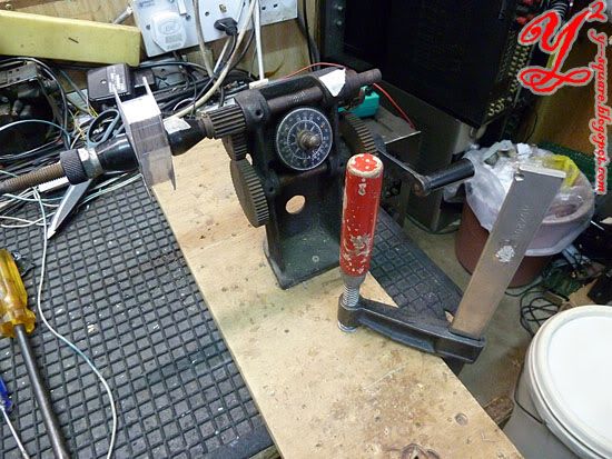
To avoid unwanted movement the device has to be stabilize.
I wasdizzy busy learning from uncle Teng (below) that I forgot to capture some steps.
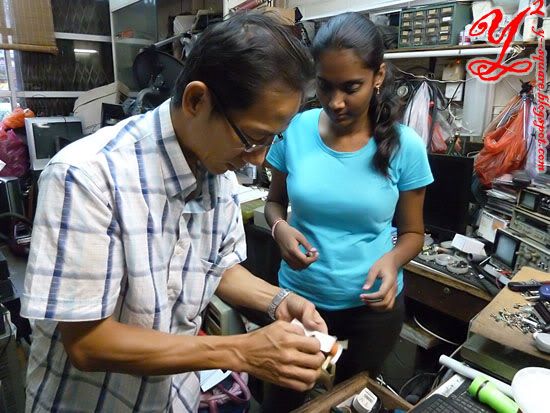
We poke holes in each edge(the model board is soft enough to be poke by needles, advantage of using model board) then have the needles to through it. 4 thread is now hanging on each edge.(I beg you can't understand , should have remember to take pictures). The intention is to tie the copper wires together tightly before taking the copper wire out from bobbin, so that It can remain in 1 piece plus remain the shape just like in the bobbin.
The winding device counts how much winding is currently hold. In this magnetic lock project, more winding is better, but the number of windings does not change the magnetic field of the core. The magnetic field is inversely proportional to the core's/winding's length. Will explain more on the calculation phase.
Then, the copper wire is insulated by tapes. Do not tape the threads in. Remove the thread on each section before rolling it with insulator aka tapes. After insulating the whole windings, and removing the threads, put the copper winding into the E core.
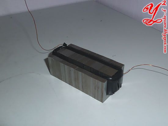
You may test your magnetic core now.
I supply 6 V of DC, as to remain 0.5A of current in the circuit.(If you supply more current rating than the copper wire can take up, it will over heat mayexplode burn)
I will show and explain more on the calculation in next few post.
Remember that bobbin I made?

It has no holes, we(suppose to me my group mate and I but the uncle helped) have to drill 1 hole in the middle, so that we can attach it to the winding device.

Drill the bobbin using electrical driller.

 It's very embarrassed that I didn't make the bobbin smooth enough, so I have to add a layer of plastic. If it happens to doing the same project, stupidly follow my previous instruction on doing the 1 time bobbin, you probably need to cover up the non-smooth surface like I did.
To avoid unwanted movement the device has to be stabilize.
I was

We poke holes in each edge(the model board is soft enough to be poke by needles, advantage of using model board) then have the needles to through it. 4 thread is now hanging on each edge.(I beg you can't understand
 , should have remember to take pictures). The intention is to tie the copper wires together tightly before taking the copper wire out from bobbin, so that It can remain in 1 piece plus remain the shape just like in the bobbin.
The winding device counts how much winding is currently hold. In this magnetic lock project, more winding is better, but the number of windings does not change the magnetic field of the core. The magnetic field is inversely proportional to the core's/winding's length. Will explain more on the calculation phase.
Then, the copper wire is insulated by tapes. Do not tape the threads in. Remove the thread on each section before rolling it with insulator aka tapes. After insulating the whole windings, and removing the threads, put the copper winding into the E core.

You may test your magnetic core now.
I supply 6 V of DC, as to remain 0.5A of current in the circuit.(If you supply more current rating than the copper wire can take up, it will over heat may
I will show and explain more on the calculation in next few post.
You may also interested in:
-How to create a magnetic lock: Phase III: Winding the bobbin, not the core

No comments:
Post a Comment